Tests and test methods according to IEC-/EN-Standard: Spelsberg
  • Products
  • Pages
  • News
  • Distributors

Tests and test methods according to IEC-/EN-Standard

The mentioned tests are based on the following standards:

  • DIN EN 60670-1 (VDE 0606-1),
  • DIN EN 61439-1 (VDE 0660-600-1),
  • DIN EN 62208 (VDE 0660-511)

with all associated amendments and extensions.

The tests described below are carried out, documented, analysed and evaluated there.

DIN EN 60670-1, VDE 0606-1

This standard applies for sockets, housings and housing parts for electrical installation equipment with a rated voltage of less than 1000 VAC and 1500 VDC, which are intended for household and similar fixed electrical installations both indoors and outdoors.
(DIN EN 60670-1, 1 Application Area)

DIN EN 61439-1, VDE 0660-600-1

This standard defines terms and specifies the operating conditions, construction requirements, technical characteristics and requirements for certification of low-voltage switch gear assemblies whose rated voltage is below 1000 VAC and 1500 VDC and which are movable or fixed.
(DIN EN 61439-1, 1 Application Area)

DIN EN 62208, VDE 0660-511

This standard applies for empty enclosures, as supplied by the manufacturer before any equipment is installed by the manufacturer of the switchgear assembly.
(DIN EN 62208, 1 Application Area)

Note:

Our in-house testing laboratory is certified according to: 

  • UL (Underwriters Laboratories)
  • DIN EN 60670-1, 60670-22, 60529

The tests described below are carried out, documented, analysed and evaluated there.

Proof of mechanical structure

DIN EN 60670-1

Lids, covers or cover plates or parts thereof

DIN EN 61439-1

Design verification of switchgear assemblies

DIN EN 62208

Type testing of empty enclosures

Proof of non-removable lids
DIN EN 60670-1:

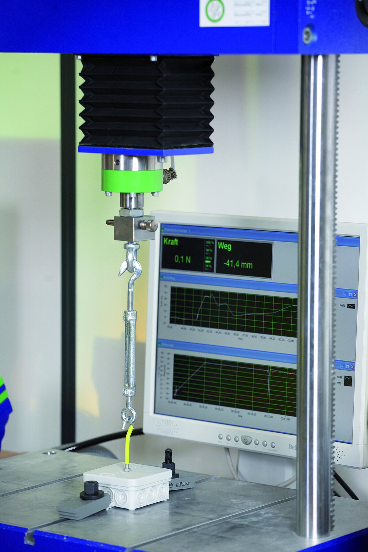
The forces are applied perpendicular to the mounting surface, at the middle of the lid, gradually increasing for one minute.

Proof of removable lids
DIN EN 60670-1:

The forces are applied ten times, gradually increasing, to the device to remove the lid. The equipment under test shall be free of damage afterwards.

Proof of resistance to ingress of solid foreign bodies

DIN EN 60670-1
DIN EN 62208, 9.8.1.2

The equipment under test is set up as in normal use and any existing cable inlets are fitted with cables. Protection is achieved if the probe cannot penetrate into the tested equipment (IP4X).

For protection level IP5X, no part of the inner surface may be covered by dust from the outside. For protection level IP6X, no dust may penetrate the into the tested equipment.(See IP code, page 309)

Proof of resistance to harmful effects of water ingress

DIN EN 60670-1
DIN EN 61439-1
DIN EN 62208, 9.8.2

The equipment under test is set up as in normal use and any existing cable inlets are fitted with cables. The equipment under test then has amounts of water applied in accordance with its protection rating (see IP code, page 309). The ingress of water is detected by lining the interior of the equipment under test with absorbent paper. The indicator paper is examined immediately after the test.

Proof of the strength of materials and parts

DIN EN 60670-1:

Mechanical strength of boxes and enclosures

DIN EN 61439-1:

Corrosion resistance of switchgear assemblies

DIN EN 62208, 9.13

Corrosion resistance of empty enclosures

Proof of heat resistance

DIN EN 60670-1:

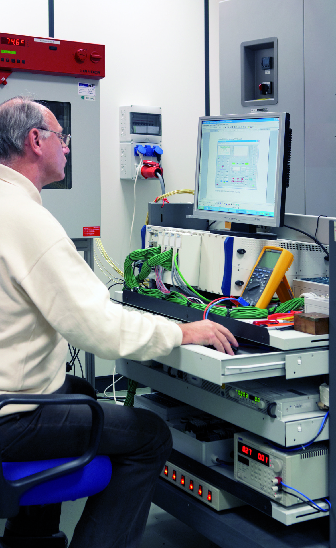
A steel ball with a 5-mm diameter is pressed down on the surface of the box or enclosure with a force of 20 ± 2 N. This formation is set up in a heating cabinet and left there for an hour at a temperature of 125 ± 2°C. After the time has elapsed, the equipment under test must be cooled to room temperature within 10 seconds by immersing it in a water tank.

Proof is furnished if the diameter of the impression left behind by the sphere is not larger than 2 mm.

Proof of durability of plastics against excessive heat and fire

DIN EN 60670-1: 
DIN EN 61439-1:
DIN EN 62208:

The resistance is determined by the glow wire test. The equipment under test is brought into contact with the hot filament for 30 seconds. The temperature amounts to:

  • 960 ± 15 °C for parts containing live components,

  • 850 ± 15 °C for cavity wall parts,

  • 650 ± 15 °C for all others.

The test is passed if the housing does not burn or glow or if the flames and the glow extinguish independently 30 seconds after removal of the glow wire. The tissue paper spread below the test set must not be ignited by falling parts.

Proof of electrical stability

DIN EN 60670-1:

Insulation resistance and electric strength of boxes and enclosures

DIN EN 61439-1:

Protection against electric shock and continuity of earth leads in switchgear assemblies

DIN EN 62208:

Proof of insulation resistance of empty enclosures

Proof of protection against electric shock

DIN EN 61439-1:

DIN EN 62208:

The test must demonstrate that all conductive parts of the device are effectively connected to the external earth lead. A resistance meter must be used here, which can supply at least 10 A. The test must result in a circuit resistance of ≤ 0.1 Ω.

Proof of electric strength

DIN EN 60670-1:

The test voltage is applied between two metal foils as for proof of insulation resistance. The test starts with about half the specified voltage and then increases rapidly to full voltage. The test is passed if no breakdown or flashover occurs.

Rated insulation voltage [V]

Test voltage [V]

Test voltage protection class II [V]

13012501875
> 130 and ≤ 25020003000
> 250 and ≤ 45025003750
> 450 and ≤ 75030004500
> 75035005250

DIN EN 61439-1:

The test voltage is applied

  • between the connected poles of the main circuit and the earthed enclosure,

  • between the unconnected poles of the main circuit,

  • between the control and auxiliary circuit and the main circuit as well as the earthed enclosure.

In order to furnish proof, the overcurrent relay must not trigger and there should be no breakdown.

Rated insulation voltage (phase-to-phase) [V]

Insulation test voltage (AC) [V]

Insulation test voltage (AC) [V]

Ui ≤ 601001415
60 < Ui ≤ 3001502120
300 < Ui ≤ 69018902670
690 < Ui ≤ 80020001830
800 < Ui ≤ 100022003110
1000 < Ui ≤ 1500---3820

Rated insulation voltage (phase-to-phase) [V]

Insulation test voltage (AC) [V]

Ui ≤ 12250
12 < Ui ≤ 60500
60 < Ui2*Ui +1000
min. 1500

Proof of clearances and creepage distances and distances

DIN EN 60670-22:

DIN EN 61439-1:

The intervals may not be less than described in Table 21 and are measured between live parts of different polarity, live parts and metal caps or sockets without insulation and live parts and the base mounting surface.

Rated insulation voltage [V]

Creepage distances, clearances and distances through
casting compound [mm]

 ≤130

1,5

> 130 and ≤ 250

3

> 250 and ≤ 450

4

> 450 and ≤ 750

6

>750

8

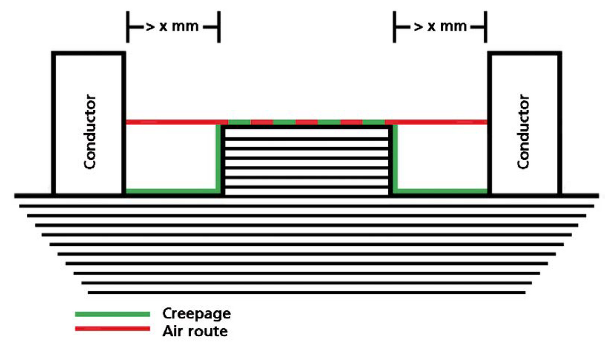
The clearances and creepage distances are evaluated as follows:

The distance x must be between 0.25 mm and 2.5 mm depending on the degree of contamination (see Table 22), otherwise it may not be used to extend the creepage. In this case, the creepage distance would be equal to the clearance, based on the example in the figure above (DIN EN 61439-1, Appendix F).

Degree of contamination

Smallest width x of grooves [mm]

1

0,25

2

1

3

1,5

4

2,5

Add product to Watchlists

Existing Watchlists

New Watchlist

organize Watchlist