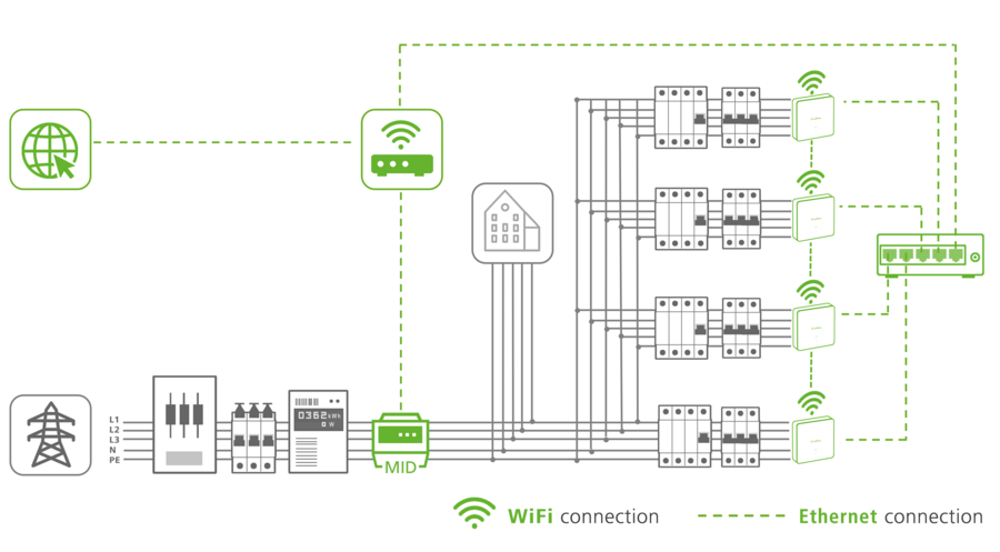
For dynamic load management to be set up, all charging stations must be part of the same network. By means of a switch and the static Ethernet configuration the wall boxes can also form their own network with no external access. More information on network integration can be found here. For configuration open the app and go to "System" - "Settings". Open "More settings" and show "Expert settings". Now select "Dynamic Load Management (DLM)". Define precisely one charging station per charging network as the DLM coordinator, to take care of coordination with the DLM charging points.
The following parameters must be set in the DLM coordinator, whereas in the individual charging points only the marked parameters need to be set. Parameters for which no setting instructions are given can be ignored in this use case.
DLM parameter overview |
App Parameter | Setting |
DLM role Coordinator/Charging point | For the coordinator select DLM coordinator For the charging points, choosing
DLM charging point (Auto Discovery) is recommended |
DLM network ID | Enter any number, e.g. 1 (ID must be identical in the coordinator and all charging stations) |
DLM coordinator connection | |
IP address of the DLM coordinator | |
Number of DLM charging points identified | Information in the coordinator for checking how many charging points are connected to the coordinator |
Sub-distribution current limit load management L1/L2/L3 [A] | This value must be set and is dependent upon the rated current of the fuse in the charging network sub-distribution. |
Mains connection current limitation L1/L2/L3 [A] | This value must be set and corresponds to the mains connection current limitation of the building (rated current of the main fuse in the building supply line). |
Maximum distributable charging current L1/L2/L3 [A] | Setting of the current available for distribution to the connected electric vehicles (≤ sub-distribution current limit load management) |
mains connection lower current limitation [A] | Minimum current that the charging process should not fall below (min. 6 A) |
Current limitation in the event of a connection failure [A] | Current limitation for each charging point, if the connection to the DLM coordinator is lost. |
Meter support for external loads | Activated |
External meter | Select built-in meter type |
IP address of the external Modbus TCP meter | A static IP address for the external meter must be stored here. This IP address must also be saved in the meter and the DHCP mode of the meter must be deactivated (see meter manual). If necessary the network router must have a setting to indicate that the meter has been assigned a static, constant IP address. |
Port of the external Modbus TCP meter | 502 (Standard - reserved for Modbus) |
Resetting of the DLM charging point database | Optional: In the DLM coordinator select "Delete", if for example a charging point has left the network and the database has to be reset |
Unbalanced load prevention | Activate |
Unbalanced load limit [A] | e.g. 16 A |
External load headroom L1/L2/L3 [A] | |
IT power supply in the DLM | |
Apply DLM offset at PV input | |
Offset at external PV input L1/L2/L3 [A] | |
Logic behaviour of the external PV input | |
External meter connection type | Select entry point |
Once the parameters have been transmitted by NFC to the wall box, the wall box performs a restart. With this, the DLM is fully set up and active.